This page is not compatible with Internet Explorer.
For security reasons, we recommend that you use an up-to-date browser, such as Microsoft Edge, Google Chrome, Safari, or Mozilla Firefox.
Your Pit Stop for Quality
Measure, Inspect, and Optimize—with Volume Graphics Software
Get Full Control from Mold to Part
Just as every millisecond in a pit stop counts in a race, every little detail counts when inspecting safety-relevant components. Volume Graphics is your pit crew. From mold to injection-molded part, from part design to inspection—Volume Graphics software gives you the insights to constantly push the quality boundaries of your plastic parts and establish efficient workflows. The software runs on data provided by the latest computed tomography (CT) technology.
Volume Graphics software enables you to identify the most important injection molding defects, whether caused by the mold or the injection molding process— quickly, easily, and with incredible accuracy. No matter how complex the shape might be, Volume Graphics allows you to sign off on processes and accurately inspect your plastic or composite parts.
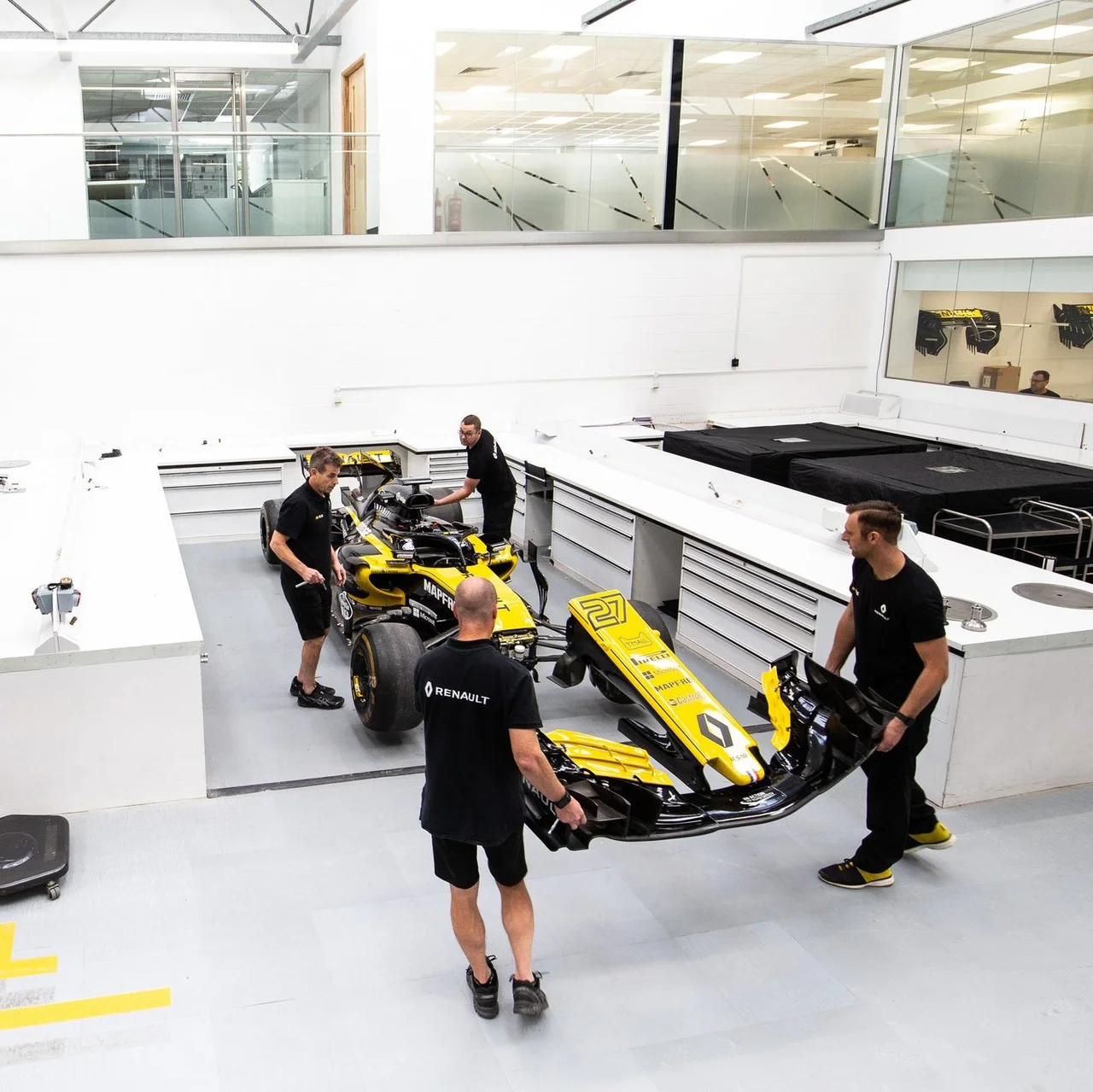
Volume Graphics and Renault F1® Team

Follow Renault F1 Team’s lead and rely on Volume Graphics’ inspection expertise: As part of a multi-year agreement, Volume Graphics is proud to support Renault F1 Team. Since 2016, Renault F1 Team has used VGSTUDIO MAX to analyze and visualize CT data. CT and Volume Graphics have since then contributed to a significant increase in the analysis capabilities of Renault F1 Team’s test laboratory.
Your Comprehensive Toolbox
Measure, Inspect, and Optimize—All with One Software
Volume Graphics supports you in all phases of injection molding, from part design and process simulation to automated inspection. With VGSTUDIO MAX, you get a comprehensive software that offers tools for geometric dimensioning and tolerancing, mold cavity correction, wall thickness analysis, nominal/actual comparison, porosity and inclusion analyses, tool optimization, volume meshing, and fiber analyses.
Dimensional Measurements
Dimensional deviations are a typical problem of all manufactured parts. Especially in injection molding, you need to measure warpage and shrinkage in the design and manufacturing phase. VGSTUDIO MAX gives you all the functionality of a physical coordinate measurement machine and more. Geometric deviations of your scanned cast part from its respective CAD data set become visible at a glance when you perform a nominal/ actual comparison.
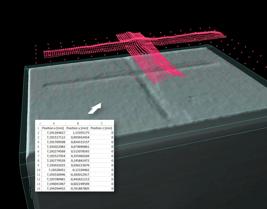
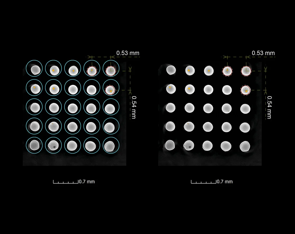
The multi-material surface determination function makes geometric dimensioning and tolerancing of multi-material objects, such as the position of metal pins of a connector relative to the plastic housing, a breeze.
By directly importing so-called Product and Manufacturing Information (PMI), which is generated by many current CAD systems, VGSTUDIO MAX saves you a considerable amount of time when you prepare measurement plans.
And to centrally store your analysis results in quality management or statistical process control software, VGSTUDIO MAX allows you to export global results of analyses (nominal/actual comparison, wall thickness analysis, porosity/inclusion analysis, and fiber composite material analysis) in the widely used Q-DAS data exchange format.

Wall Thickness Analysis
Wall thickness influences the behavior of the melt front and the homogeneity of the temperature in the part during filling and cool down. With VGSTUDIO MAX, you can determine the actual wall thickness, which gives you more insight into potential problems that can cause warpage. You can quickly and automatically measure wall thickness or gap width for near parallel surfaces (ray method) as well as for curved or branching surfaces (sphere method).

Porosity and Inclusion Analyses
The melt front can entrap air, which results in pores, and burnt material, or contaminated raw material may produce inclusions in injection-molded parts. With VGSTUDIO MAX, you can locate pores, holes, cracks, and inclusions and get detailed quantitative information and statistics on these defects.
Tool Optimization
Injection-molded parts shrink and warp due to the material and heat distribution and cool-down behavior. VGSTUDIO MAX analyzes the deviation in order to export compensated surfaces for the mold maker. By adding the compensated warpage deviation to the shrinkage information, the output can be used to update and optimize the mold with minimal tool rework. Quality control includes draft angle and curvature analyses. It can also reconstruct surface patches by shrink wrapping it to the scan or the mold.
You can use the Manufacturing Geometry Correction Module in combination with the golden surface function to correct a mold with multiple identical nests. The golden surface function creates an average surface of the parts coming from the different nests, which is the best basis for correcting the nest geometries.
Fiber Analyses
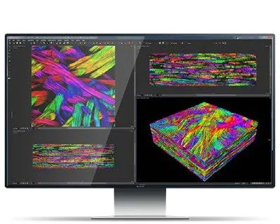
Injection molding of fiber-reinforced compounds requires the control of the fiber orientations that determine the mechanical properties of the component. Fiber orientations and fiber volume fractions can be derived from CT scans and mapped onto existing volume meshes in the PATRAN ® or NASTRAN ® format—either for direct use in FEM simulations or for validation of fiber distributions from injection molding simulations. A dedicated format for export into Digimat® is available.
Efficient Repetitive Inspections
Mass-produced components, as they occur in injection molding, lead to repetitive analysis tasks. VGSTUDIO MAX allows you to save valuable time by automating them.
To efficiently analyze multiple cavities of a connector, you can copy measurement plans and analyses (e.g., a defect analysis, nominal/actual comparison, or wall thickness analysis) from one cavity to a periodic cavity pattern in one go. For the efficient inspection of multiple identical parts, you can—in one go—apply macros to multiple identical objects in one scene. Multiple identical parts in separate (.vgl) files can also be efficiently analyzed using batch processing.
Automated Inspection in Production
It is becoming increasingly important for parts to be inspected as comprehensively and non-destructively as possible directly where they are produced. With VGinLINE, you can semi- or a fully automate the quality control process of plastic parts (including the automatic recognition of tool cavity markers).
VGinLINE is a ready-to-use framework that relies on the advanced capabilities of VGSTUDIO MAX. It can cover the whole process from the reconstruction of the CT data to inspection, reporting, and manual review. Its modular architecture makes it easy to tailor it to specific scenarios. You can combine analyses and any other required data, such as report configurations or reference models, into a single inspection plan, which you can edit in VGSTUDIO MAX and execute in VGinLINE.
Why CT?
The Most Reliable Technology for 3D Inspection

Computed tomography (CT) data provides a comprehensive view of the injection molded part because of its ability to accurately represent both surfaces and inner structures. In combination with VGSTUDIO MAX, CT offers the unique possibility of getting a full understanding of a part’s quality.
Because CT reconstruction produces a complete representation of a component in 3D based on a large number of 2D X-ray images, CT allows the user to draw conclusions on the external and internal structures of a component and its material properties. Thus, CT can answer more complex questions than tactile or optical inspection methods.
While tactile coordinate measurement methods are also non-destructive, CT is also non-intrusive. This means measuring with CT doesn’t deform the part. And unlike optical methods, CT still works accurately even if the part reflects or is translucent.
Volume Graphics offers a fully integrated CT reconstruction function, which works equally well with different CT systems from different manufacturers. Most major CT system providers sell Volume Graphics software together with their hardware. In addition, we rely on a worldwide network of distributors to serve our customers around the globe.
Stay Informed
Subscribe or follow Volume Graphics to stay up to date on all Swiss Plastics Expo 2020 news:
