This page is not compatible with Internet Explorer.
For security reasons, we recommend that you use an up-to-date browser, such as Microsoft Edge, Google Chrome, Safari, or Mozilla Firefox.
The dimensional metrology features of Volume Graphics software turn your computed tomography (CT) scanner into a coordinate measuring machine. Volume Graphics software delivers metrology results on voxel, mesh, point cloud, and CAD data that conform with ISO 5459 and ISO 1101. The algorithms used to fit geometry elements to the extracted surfaces have been verified by the German National Metrology Institute PTB and NIST, the National Institute of Standards and Technology of the United States Department of Commerce.
Dimensional Metrology Features
Surface Determination
All CT-based metrology depends on an accurate surface determination in the voxel model. The better the surface determination, the smaller the measurement uncertainty.
The Volume Graphics surface determination:
- Ensures minimum measurement uncertainty.
- Is subvoxel-accurate and locally adaptive, making details measurable that are smaller than a voxel.
- Processes gray values of individual voxels depending on the gray values of the surrounding voxels, which makes the surface determination markedly more accurate than relying on a single greyscale threshold value.
- Offers an interval-based mode that allows for a high-accuracy, locally adaptive surface determination, even within an automated environment and with changing gray value conditions.
- Offers a multi-material mode that allows for simultaneous determination of the surfaces of multiple materials within a volume, resulting in one component per material.

File I/O
Volume Graphics software lets you work with any type of geometry data—computed tomography data as well as CAD, mesh, and point cloud data.
Volume Graphics software:
- Supports CT data from various vendors.
- Imports point cloud and meshes in STL, OBJ, and PLY files, including textured meshes and colored point clouds.
- Understands all neutral CAD data types (STEP and IGES) in its basic edition.
- Automatically translates CAD views into bookmarks.
- Repairs and optimizes corrupt CAD and mesh data during import.
- Offers enhanced auto-completion modes.
- Replaces CAD geometries with matching geometry elements such as planes, cylinders, etc.
- Imports native CAD files from CATIA, JT, Unigraphics/NX, Creo, SolidWorks, and Solid Edge with the CAD Import Module.*/**
- Supports PMI Import (Product and Manufacturing Information) for all major CAD formats providing additional part information such as dimensions, GD&T, layers, annotations, and captions (MBD, model-based definition). Processes can be automated using macros, batch processing, and templates.***
- Saves a considerable amount of time, since measurement plans do not have to be created manually from technical drawings anymore.
- Increases efficiency of your quality control by smart conversion of PMI data.
* CAD translation technology supplied by Tech Soft 3D
** Supported CAD formats of the CAD Import Module: CATIA V4 (up to 4.2.5), CATIA V5 (up toV5 6R2023), JT (up to 10.9), Unigraphics/NX (Unigraphics 11 to NX2406), Creo (up to 10.0), SolidWorks (97 to 2024), Solid Edge (2019 to 2024).
*** Semantic PMI import supported by the CAD Import with PMI Module for CATIA V5, Creo, and Unigraphics/NX
Alignment
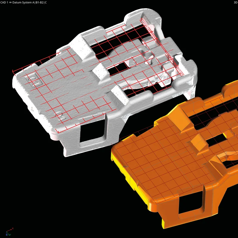
Alignment to a nominal part or a coordinate system is crucial for measurement results. It enables the extraction and comparison of nominal and measured dimensions and the investigation of assemblies.
With Volume Graphics software, you can:
- Align any data set to a reference data set or a coordinate system using point-, surface-, and geometry-based approaches:
- Point-based: RPS and 3-2-1 alignment.
- Surface-based: Best fit, also with constraints or partial areas, as well as feature-based, focusing on characteristic areas.
- Geometry-based: Sequential alignment allows for the imitation of physical alignments, creating corresponding pairs of geometry one after another, decreasing more and more degrees of freedom. Remaining degrees can be fixed with a best fit for the whole or partial model.
- Tolerance alignment results to determine their quality.
- Use custom and local coordinate and datum systems, providing automated measurement updates when changing alignments.
- Use a non-rigid alignment as part of the Manufacturing Geometry Correction Module.
Nominal/Actual Comparison*
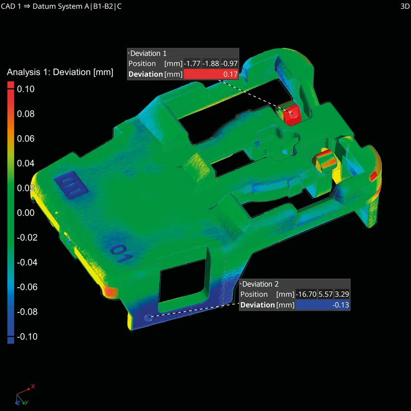
Get an easy-to-understand visualization of deviations of your scanned object from a reference data set.
The nominal/actual comparison features:
- Give you a color-coded comparison between voxel, CAD, and mesh data (also referred to as false color plot).
- Allow you to position annotations individually, tolerate them, and place min./ max. information automatically.
- Statistically analyze a full part or rule-based created components.
- Have an adjustable color bar for smooth or stepped color transitions and transparent areas.
- Offer hairline rendering in 2D slices.
* Requires the Coordinate Measurement Module
Geometry Element Fitting
Extracting geometry elements from scans is the basis for evaluating dimensions and tolerances.
Volume Graphics software enables you to:
- Extract geometry elements from scans.
- Automatically recognize the type of geometry element using "Smart Expand."
- Control geometry element fitting by border distance, density, angular deviation, fit method (like Gauss or Chebycheff), and constraining to a position or axes.
- Use algorithms certified by PTB and NIST*.
* PTB- and NIST-verified: This software contains the Volume Graphics Metrology Kernel VGMK 2023.1.0, which passed the PTB test for “Evaluation software based on minimum-zone method for coordinate measuring machines” and the PTB test for “Evaluation software based on least-squares method for coordinate measuring machines” , and which was verified by the NIST “Algorithm Testing and Evaluation Program for Coordinate Measuring Systems”. The test results were obtained under Windows (64 bit).
Dimensional Measurement
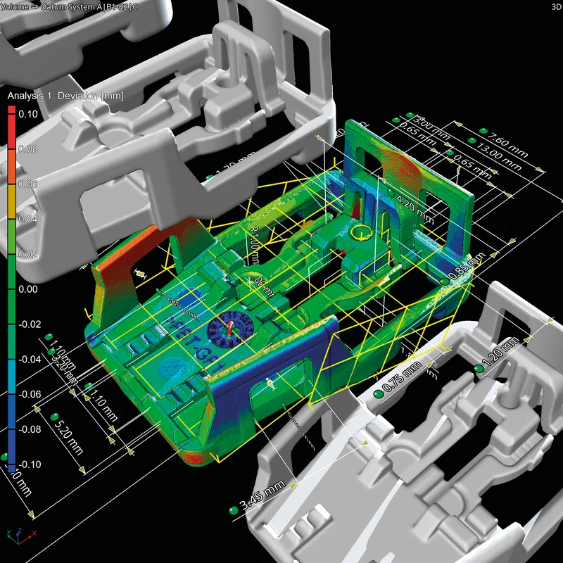
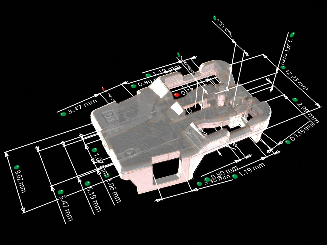
In Volume Graphics software, you can measure 2D and 3D dimensions with standardized or individual tolerance tables that even automatically set name, dimension, and tolerance by balloon number. Volume Graphics gives you all the functionality of a physical coordinate measurement machine, optical scanner, and more.
With the functions for dimensional measurement, you can:
- Create dimensions such as distances, angles, and radii in both in 2D and 3D, simply by selecting geometry elements on the screen, in the Scene Tree or in the tabular overview of all elements.
- Assign tolerances from nominal CAD, PMI information, individual values or tolerance tables.
- Extract and report values in any projection direction.
- Use sophisticated filter functions for very large measurement plans to locate features and their children in the scene tree.
- Use instruments for quick, point-to-point-based distance and angle analyses and annotations.
GD&T
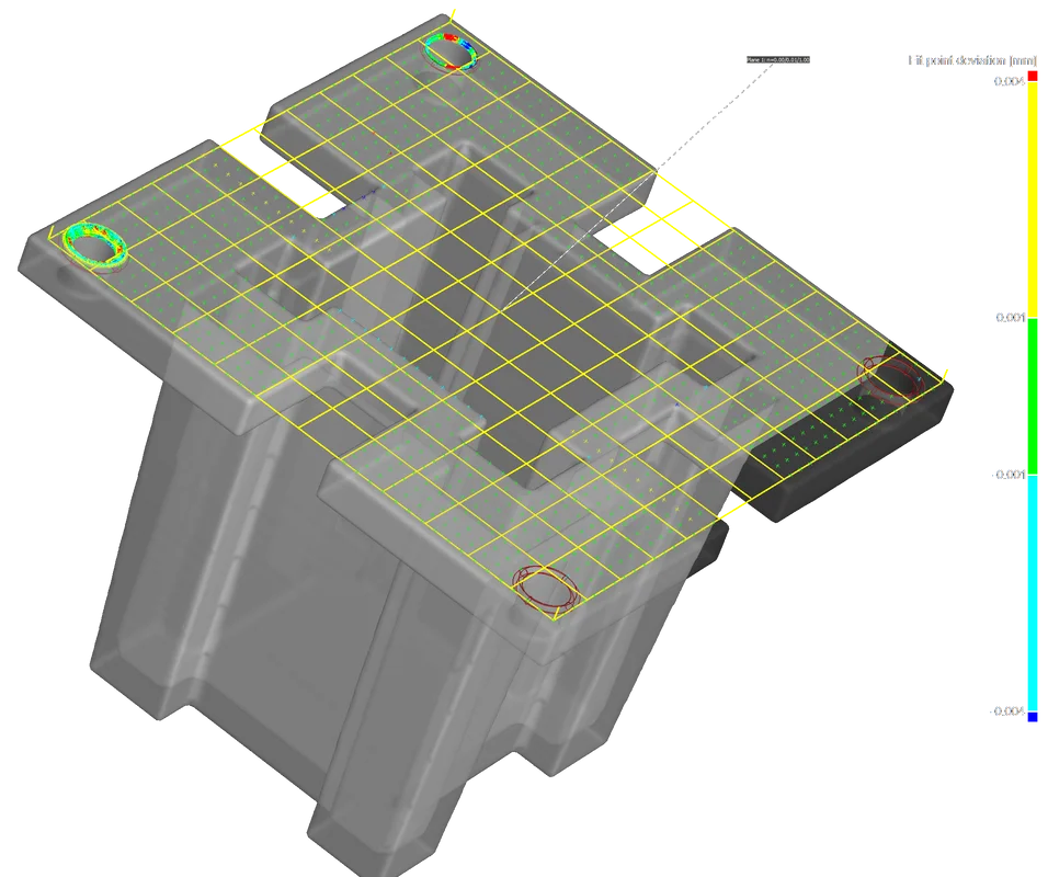
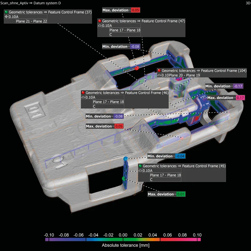
Volume Graphics software supports all 17 Geometrical Dimensioning and Tolerancing (GD&T) callouts, such as line and surface profile as well as position with maximum material requirement (MMR).
The GD&T functions:
- Support all GD&T callouts.
- Are ISO or ASME norm compliant and continuously updated.
- Support complex (free-form) datums, line/surface profile analyses, and min./max. material conditions.
- Support local coordinate and datum systems.
- Allow you to visualize GD&T analyses, where possible, as easy-to-understand color overlays.
- Allow you evaluate the overall geometrical analyses in a user-friendly way by simultaneously displaying all complex GD&T information with a relative color map.
- Can overlay surface profile callouts with and without datum systems and visualize results at the same time.
- Enable you to interpret the value and direction of position deviations based on visual clues given by the software.
Shape-Following Adaptive Measurement Templates
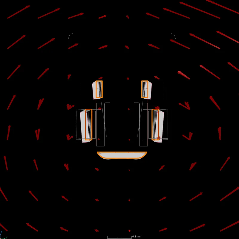
Save 50% or more time with adaptive measurement templates that follow the shape of distorted parts. First articles of injection-molded parts and 3D-printed parts are often not only out of tolerance but warped in such a way that a measurement plan created on the nominal CAD object cannot be applied to the scanned part. With adaptive measurement templates, a measurement plan created using the nominal CAD data or imported via PMI can be easily applied to even strongly deformed parts. The measurement points are placed at the optimal positions on the actual part and perfectly follow the distorted shape.
You no longer need storage systems or time-consuming manual post-processing of features by highly skilled users. This new, patented technology makes it possible to apply dimensions and tolerances to distorted parts where otherwise only local coordinate systems would permit a correct analysis.
Wall Thickness
Perform volumetric analyses of a part’s thickness quickly and automatically—either using the ray method for parts with simple shapes or the sphere method for more organic shapes, including complex 3D printed parts. Color-coded results help you localize areas with an insufficient or excessive wall thickness or gap width within the voxel, point cloud, mesh, or CAD data set.
The wall thickness analysis features:
- Automatically and quickly analyze the wall thickness.*
- Offer two different, dedicated methods for cubic and organic parts, respectively:
- For parts with near-parallel surfaces, the ray-based method delivers the best results.
- For organic, curved or even branching surfaces, the sphere method is preferable, especially for complex 3D printed shapes that are topology optimized, generatively designed or even lattice structures.
- Locate areas with an insufficient or excessive wall thickness or gap width automatically and directly within the voxel, point cloud, mesh, or CAD data set.
- Allow the application of tolerances with various parameters, e.g., thickness (minimum, maximum, mean, deviation).
- Reduce the number of false detections with a noise filter, which is especially helpful for automated inspections.
* Use in combination with Coordinate Measurement Module recommended

Workflows and Automation
When dealing with repetitive measurement tasks, powerful automation functions are at your side to help speed up your work.
Volume Graphics software allows you to:
- Fully automate multi-part inspection using macros and batch processing, with VGinLINE also available for fully automated, 24/7 inline applications.
- Automatically generate measurement templates from imported PMI in native CAD files, which can be shared throughout the corporation.
- Automatically identify canonical geometries on scans and CAD models with one click using the "Smart Expand" functionality.
- Define GD&T analyses and dimensions either on CAD or on scans in order to create measurement plans from technical drawings.
- Transfer measurement plans between all representations, e.g., to create a measurement template on a scanned master model that could significantly differ from a CAD model.
- Pattern single features or whole measurement plans onto periodic structures to avoid replicating tasks.
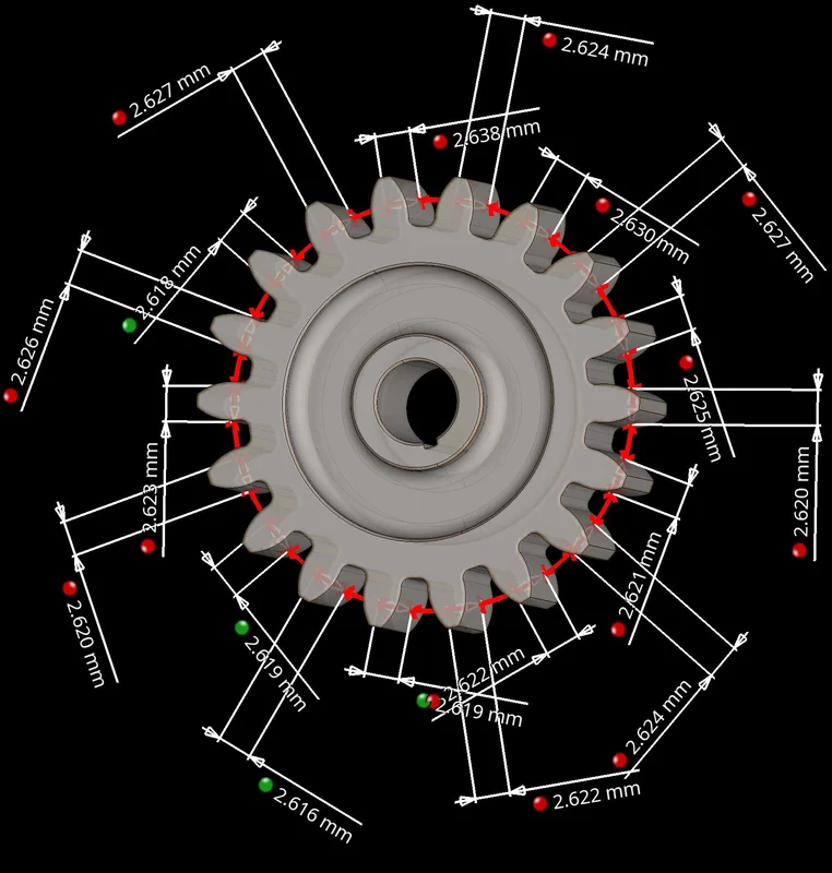
- Mirror measurements or create helical structures for threads and gears.
- Pattern recurring geometries along a helical path, for example, to measure threads and gears.
- Record macros containing alignments, measurement templates, evaluations, and interaction to apply them to multiple parts and to export them whole or in part for full automation in VGinLINE.
- Save and exchange your metrology projects in the lightweight *.mvgl file format, which is up to 20 times smaller than the original data size without sacrificing measurement quality.
Reporting
Reporting is crucial for the documentation of metrology results. Volume Graphics provides different reporting tools for sharing information.
Volume Graphics software allows you to:
- Export images (color-coded in 2D and 3D), histograms, and data tables in common file formats to work with them in other applications.
- Edit and view reports in a WYSIWYG (What You See Is What You Get) editor exactly as they will appear in the PDF, customize them, automate their creation, and store them directly in your *.vgl project.
- Create comprehensive and completely customizable test reports hand-in-hand with Microsoft Excel (requires Microsoft Excel).
- Export complete coordinate measurements results in the Q-DAS format to use as input values in other applications, for example for statistical process control.

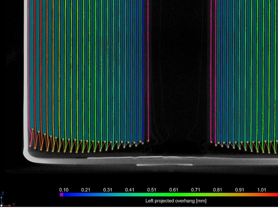
Battery Anode Overhang Analysis
Discover how computed tomography can be harnessed to nondestructively evaluate battery cells. Our new Battery Analysis Module offers advanced, precise measurements of the anode overhang, accurate tolerancing of electrode shape and ordering, and seamless automation of all functions.
Benefits
Accurate
- Unique, locally adaptive, and sub-voxel precise surface determination
- Surface representation directly on the CT data, no loss of accuracy from conversion to a surface mesh
- PTB- and NIST-verified fitting of geometry elements on CT data
Efficient
- Import of PMI measurement plans directly from CAD models
- Automated replication of measurement plans across periodic structures
- Automated execution of measurement plans and reporting both in the lab/office and in production
- Compact file format for easily sharing data
Universal
- Hardware independent: Can be combined with almost any CT or optical scanner
- Handles voxel, point cloud, and mesh data
- Leading software for all industrial CT analyses, including metrology, defect analyses, and material structure analyses